Datos de componentes, equivalencias y mas.
Si necesitas buscar datos de un componente, sus equivalentes, opciones de reemplazo y artículos sobre los mismos, este es tu sitio.
Si necesitas buscar datos de un componente, sus equivalentes, opciones de reemplazo y artículos sobre los mismos, este es tu sitio.
Cuando vas a crear algún cacharro con un microcontrolador PIC, te serán de gran ayuda las Notas de Aplicación de Microchip, en las que puedes encontrar gran cantidad de información sobre como interconectar circuitos, «trucos», circuitos adicionales, etc…
Identificar que es un componente SMD puede ser muy complicado. En esta página tienes una relación muy completa de los códigos utilizados que sin duda te ayudará en esta tarea.
Una vez que has creado u obtenido el diseño de una placa de circuito impreso, tienes que llevarla al mundo real, hay muchos métodos para ello, unos rápidos y sucios, otros laboriosos y profesionales. En esta sección de Instructables, se recopilan multitud de métodos para que puedas elegir el que mas te guste o convenga.
Esta entrada contendrá sitios que voy encontrando y que son interesantes para adquirir módulos para prototipos, componentes, etc…
BricoGeek: Arduino, módulos, componentes, motores, etc…
Cooking Hacks: (de Libelium): ZigBee, Xbee, Arduino, módulos, kits, prototipos, etc…
Seeed Studio Bazaar: Arduino, ZigBee, Sensores, Robótica, Herramientas, etc…
Si necesitas una información básica sobre configuraciones de filtros EMI/RFI, aquí tienes una pequeña referencia, están los filtros en PI, LC, CL y T.
Starlino es una página donde encontrarás proyectos, trucos y artículos de electrónica aplicados a la robótica, componentes y dispositivos.
En este sitio (en francés), hay muchísimos proyectos totalmente desarrollados con PICs incluyendo esquemas y código fuente.
First, I know my english is not perfect. If you want to contribute sending me a better redaction, you’re welcome to send.
IN CONSTRUCTION – AKA: INCOMPLETE!
One week ago, in the TNT-audioaddicts group from Yahoo! groups, an user started a thread about building an strobe for his turntable. There was discussed the fact that neons that turntables brings light twice every mains cycle (the + and – of it ). The person started it offered as a solution for this using 2 leds each polarized in one way. This has some problems:
I proposed the built of a led+microcontroller-quartz controlled strobe light source, and here it is.
I’ve used two tools for developing this and both can be obtained free of charge with enough features for this project (limited versions but not time limited):
Also, you’ll need a programmer for the PIC, if you have one or know anybody has one use it, if you can’t get one, search the web for an easy to build-cheap one. There are lots of designs in the Internet, just search for one you like. For example search for JDM programmer, and build the one you like (but be sure it programs the PIC12F629!). For programming the PIC you can use Winpic800 or ICProg.
The circuit is very simple, just the PIC, the power it need to work, the MCLR supply (this doesn’t have a reset button), a jumper to select 50/60 Hz simulation, and the LED. It can be powered for anything between 3V and 5V, but beware, the current limiting resistor for the LED is calculated for 3V, see below to calculate the value if you want to use an higher voltage.
Notes about the LED:
The schematic:
As i said before the schematic for StrobLED is pretty simple, only complicated 😀 by the use of the quartz crystal, but as we need precision for this is better use it instead the built-in oscillator. I’m using 8Mhz instead 4Mhz to get more control over the delays used to blink the LED, i’m using 8Mhz instead 20Mhz to save power if you use batteries.
This is simple:
The PCB:
NOTE I’VE NOT BUILD THE PCB for now, it may be wrong, i’ve test the StrobLED in a breadboard. If you have doubts don’t build it until i remove this warning.
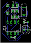
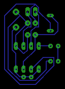
This is a little one (could be smaller using SMD components, but complicated to mount!). I think this size can be installed in any place in your turntable (if you want to do that) or in a little box+2AA batteries and use «by hand».
The PCB with components placed:
And the routes:
Later i’ll post both schemas and PCB in Eagle format and PCB in PDF also.
PCB Update.
As the previous PCB has very narrow traces, it may be difficult to make it for a hobbyst, so i’ve make another PCB design with thicker ones and built it with a CNC Mill. Here it is:
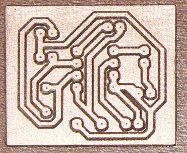
The V.2 Layout:
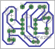
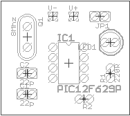
The V.2 PCB:


V.2 Component side:
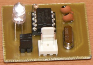
Finally i assembled the StrobLED in the PCB above.
Here is a picture of it with the Hz jumper installed (then it would run at 120 Hz, so it simulates 60Hz AC)
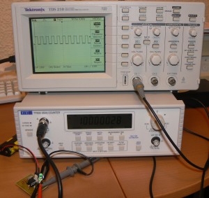
The oscillator performs very well. Here is running at 100(50)Hz. (Click the image to see full size).
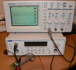
Also running at 120(60)Hz. (Click the image to see full size).
How it works with an strobe disc? Well as my Revolver turntable has not an Strobe (nor adjustements), i only can cut a Vinyl Engine one and take a picture (long exposure) to show it works: (Click to enlarge).
The code:
The code is writed in MikroBasic and now i’ll post it later (must cleanup it 🙂 and add the frequency routine (now it works at fixed 50Hz))
Calculating R1
The R1 resistor is placed to limit the current throw LED1 and of course the pin GPIO of the microcontroller. If you change the LED and/or the power supply voltage, you must recalculate its value, but don’t be scared, is very simple.
By Ohm’s law, the current throw a circuit is the same in all, and it is R=V/I (R in ohms, V in volts, I in amps), then you must calculate R to limit the current throw this way:
Imagine you decide to use a LED that has a forward voltage of 1.9V and a forward current of 20mA, look no more: is this one.
Imagine also you decide also power StrobLED with 4.5V instead 3V (ie. 3xAA batteries).
The calculation is:
R=V (4.5-1.9)/A (0.02)
You must substract from voltage, the voltage drop of the led (AKA forward voltage), and we passed mA to A (by dividing by 1000) so R:
R=2.6/0.02 = 130 ohm
The nearest commercial (by up) value is 150 ohm, so choose it. To calculate the disipated power (and resistor power) the formula to use is W=V*A, being V=The diference between power supply voltage and LED drop (2.6 as we calculated before) and A is the current throw it (remember, the same in all the circuit):
W=2.6*0.02= 0.052W, so a 0.25W (1/4 W) resistor will be enough.
For this LED and using the StrobLED with 4.5V you must replace R1 with a 150 ohm, 1/4W resistor.
Will continue….
If your turntable hasn’t a strobe disk just get one from Vinyl Engine, print it, carefully cut it, more carefully make the center hole, and you’re done!
License:

StrobLED by Jose Maria Terry is licensed under a Creative Commons Attribution-Noncommercial-Share Alike 3.0 Unported License.
Permissions beyond the scope of this license may be available at http://www.automati-k.com.
Electrónica Unicrom es un sitio que compila mucha información sobre teoría electrónica y explicación de componentes. Las explicaciones están muy claras, si quieres saber los fundamentos de algo relacionado con la electrónica es un buen sitio para comenzar.